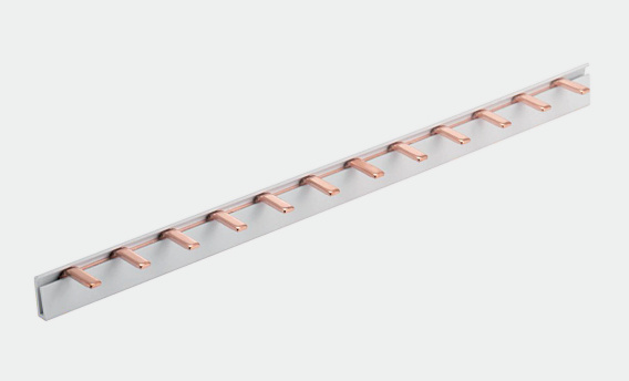
Standard Comb Busbars
Pin Type Copper Comb Busbars
1–4 poles · 40–80 A · 18 mm tooth pitch
Pin Type copper comb busbars in 1P, 2P, 3P and 4P layouts, with 6–16 mm² sections and model ratings of 40–80 A.
Models & dimensions →A precise fit.
A clearly specified panel.
Compare pin, C45, U-fork, compact DPN and grouped connection layouts. Model ratings, conductor sections and original dimensional drawings are organised together for practical selection.
Browse all families ↓Compare contact layouts →
| Family | Connection / arrangement | Model current range |
|---|---|---|
| CS101–CS104 → | Pin · 1P–4P · 18 mm adjacent pitch | 40–80 A |
| CS201–CS204 → | C45 · 1P–4P · 18 mm adjacent pitch | 40–80 A |
| CS301–CS304 → | U-fork · 1P–4P · 18 mm adjacent pitch | 40–80 A |
| CS201D–CS204D → | C45 D · 1P–4P · 1,000 mm length | 32–100 A |
| CS401–CS403 → | C45 L · grouped layouts | 32–70 A |
| CS404 / GK404 → | Six distinct grouped layouts | 63–150 A |
| CS601 / CS602 / CS3P → | DPN / DPNLE / 3P+N · 9 mm local spacing | 32–70 A |
| CS501LE–CS504 → | C65 LE · four grouped layouts | 40–70 A |
| CS2P · DZ108 · CS808 · BV2 | Dedicated device-group contact patterns | 63 A |
| CS end caps → | Standard / E / D insulation profiles | Accessory |
Current ranges describe the models within each family, not every configuration. The 150 A option is GK404-3 in the 3P 2 layout. Group-span dimensions and adjacent tooth pitch are different measurements.
Search an exact code such as CS203D-6, GK404-3 or CS310E. Each family page connects the model table with its dimensional layout.
13 product families
1–4 poles · 40–80 A · 18 mm tooth pitch
Pin Type copper comb busbars in 1P, 2P, 3P and 4P layouts, with 6–16 mm² sections and model ratings of 40–80 A.
Models & dimensions →1–4 poles · 40–80 A · 18 mm tooth pitch
C45 Type copper comb busbars in 1P, 2P, 3P and 4P layouts, with 6–16 mm² sections and model ratings of 40–80 A.
Models & dimensions →
1–4 poles · 40–80 A · 18 mm tooth pitch
U Type copper comb busbars in 1P, 2P, 3P and 4P layouts, with 6–16 mm² sections and model ratings of 40–80 A.
Models & dimensions →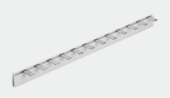
1,000 mm length · 1–4 poles · 32–100 A
CS201D–CS204D one-metre copper comb busbars with 1–4 pole layouts, detailed profile dimensions and 32–100 A model options.
Models & dimensions →
Grouped tooth layouts · 32–70 A · 6–13 mm²
CS401, CS402 and CS403 grouped C45 busbars with 45, 63 and 99 mm dimensioned group spans and model ratings from 32 to 70 A.
Models & dimensions →
6 distinct layouts · 63–150 A · CS404 / GK404
CS404 and GK404 grouped copper busbars cover six contact layouts, including 3P+N, 4P-L, 4PLE and DZ158 patterns, with 63–150 A model ratings.
Models & dimensions →
9 mm local spacing · DPN / DPNLE · 32–70 A
CS601 DPN, CS602 DPNLE and CS3P 3P+N busbars use compact 9 mm contact spacing, with model-specific ratings from 32 to 70 A.
Models & dimensions →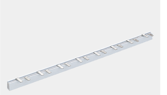
C65 LE layouts · 40–70 A · 6–13 mm²
C65 LE-series copper busbars include CS501LE, CS502, CS503 and CS504 layouts with 40–70 A options and grouped 18 mm contacts.
Models & dimensions →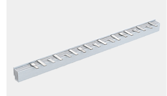
63 A · 10 mm² · 2P three-phase layout
Grouped comb arrangement for the CS2P two-pole / three-phase device layout.
Models & dimensions →
63 A · 10 mm² · DZ108 fork layout
DZ108 copper comb busbar with fork contacts, a 10 mm² conductor section and a 63 A rating.
Models & dimensions →
63 A · 13 mm² · CJX2 contactor layout
CS808 copper comb busbar for CJX2-format contactor layouts, with a 13 mm² conductor section and a 63 A rating.
Models & dimensions →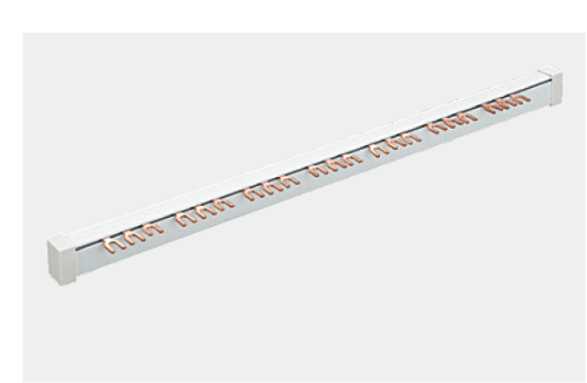
63 A · 10 mm² · BV2 grouped fork layout
BV2 grouped fork copper busbar with a 45 mm contact-group span, a 10 mm² conductor section and a 63 A rating.
Models & dimensions →
1–4 poles · Standard / E / D · 13 article numbers
CS-series insulating end caps for 1–4 pole comb busbars, including standard, E-profile and three-pole D-profile versions.
Models & dimensions →No matching family. Try a shorter model code or clear the type filter.
Match pin or fork shape, contact width and height, device pitch and the space required by accessories. Check the entire row, including gaps between groups.
Map each contact to its intended phase or neutral. Keep separate circuits and residual-current device groups separate in the busbar arrangement.
Select the model current, feed arrangement and protective device together. Finish exposed ends and unused contacts with correctly matched insulating components.
A comb busbar distributes power along a row of compatible electrical devices through repeated copper contacts inside an insulating profile. Pole arrangement defines the electrical sequence; tooth geometry defines the mechanical connection.
The contact shapes differ. CS101–CS104 use pin contacts, CS201–CS204 use the C45 contact profile, and CS301–CS304 use U-fork contacts. Compare the actual tooth drawing and the terminal opening before selecting a format.
No. Check contact height, width, terminal position, phase sequence and insulation profile as well as pitch. Grouped layouts have deliberate gaps that must match the device row.
Feed position changes the current carried by individual bar segments. It does not automatically increase the rating of the feeder terminal, connected devices or assembly. Use a rating valid for the complete feed arrangement; do not apply a generic multiplier.
No. End caps close the insulating profile at the bar ends. Tooth covers protect unused exposed contacts. Select each accessory for its intended position and matching profile.
Provide the full model code and layout, quantities, length or tooth count, matching device family, end-cap requirements, destination and packaging needs. For CS404, include the layout designation because several geometries share a model number.
Include model codes and layouts, required length or tooth count, matching device series, quantities and end-cap requirements.