PRIVATE DESIGN PREVIEW Product data and supply terms are being verified. RFQ lists stay in this browser.
Wenzhou Changsong Electric Co., Ltd.
Catalogs & technical filesContact & inquiryEN
CHSOINDUSTRIAL ELECTRICALRequest a quote 0→
C45 & C65 Layouts

C65 LE-Series Copper Comb Busbars

C65 LE-series copper busbars include CS501LE, CS502, CS503 and CS504 layouts with 40–70 A options and grouped 18 mm contacts.

C65 LE layouts40–70 A6–13 mm²
C65 LE-Series Copper Comb Busbars
CS501LE–CS504 · C45 & C65 Layouts
Technical data

Product specifications

Select the C65 LE layout by the device group width, then order the CS501D, CS502D, CS503D or CS504D model shown in its table. Preserve the gaps between repeated groups.

CS501LE–CS504 technical specifications
ParameterSpecification
Product familyCS501LE–CS504
ConductorCopper
Nominal voltage415 V
Maximum operating voltage500 V
Impulse voltage4 kV
Rated current40–70 A; select by model
Connection arrangementSee the pole layout and terminal geometry for each configuration
Model selection

Ratings, contact patterns & dimensions

All dimensions are in millimetres unless stated otherwise. Conductor cross-section is in mm²; the model-table width is distinct from contact tooth width.

The family names are CS501LE / CS502 / CS503 / CS504; the ordering-model tables use the D suffix. Include the full ordering code and layout together.

CS501LE · C65 1P-LE

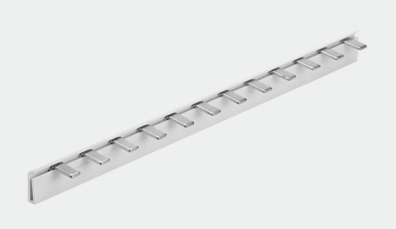
CS501LE · C65 1P-LE copper busbar
CS501LE · C65 1P-LE product configuration
CS501LE · C65 1P-LE dimensional drawing and contact arrangement
Contact geometry · Dimensions in mm
CS501LE · C65 1P-LE model ratings
Ordering modelCopper thickness (mm)Cross-section (mm²)Rated current (A)Conductor width (mm)
CS501D-11.26405
CS501D-21.510637
CS501D-31.513709
Layout designation
C65 1P-LE
Local contact spacing
18 mm
Dimensioned group span
54 mm
Contact width
6 mm

CS502 · C65 2P-LE

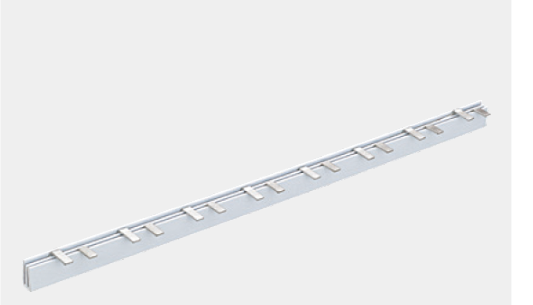
CS502 · C65 2P-LE copper busbar
CS502 · C65 2P-LE product configuration
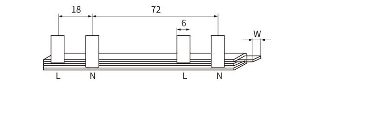
CS502 · C65 2P-LE dimensional drawing and contact arrangement
Contact geometry · Dimensions in mm
CS502 · C65 2P-LE model ratings
Ordering modelCopper thickness (mm)Cross-section (mm²)Rated current (A)Conductor width (mm)
CS502D-11.510637
CS502D-21.513709
Layout designation
C65 2P-LE
Local contact spacing
18 mm
Dimensioned group span
72 mm
Contact width
6 mm

CS503 · C65 3P-LE

CS503 · C65 3P-LE copper busbar
CS503 · C65 3P-LE product configuration
CS503 · C65 3P-LE dimensional drawing and contact arrangement
Contact geometry · Dimensions in mm
CS503 · C65 3P-LE model ratings
Ordering modelCopper thickness (mm)Cross-section (mm²)Rated current (A)Conductor width (mm)
CS503D-11.26405
CS503D-21.510637
CS503D-31.513709
Layout designation
C65 3P-LE
Local contact spacing
18 mm
Dimensioned group span
116 mm
Contact width
6 mm

CS504 · C65 4P-LE

CS504 · C65 4P-LE copper busbar
CS504 · C65 4P-LE product configuration
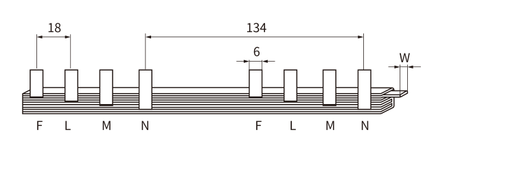
CS504 · C65 4P-LE dimensional drawing and contact arrangement
Contact geometry · Dimensions in mm
CS504 · C65 4P-LE model ratings
Ordering modelCopper thickness (mm)Cross-section (mm²)Rated current (A)Conductor width (mm)
CS504D-11.26405
CS504D-21.510637
CS504D-31.513709
Layout designation
C65 4P-LE
Local contact spacing
18 mm
Dimensioned group span
134 mm
Contact width
6 mm
Application & installation

Fit the complete device row

Application fit

  • C65 LE-format device groups matched by terminal drawing
  • Panel rows requiring 54, 72, 116 or 134 mm dimensioned group spans

Ordering checklist

Select the C65 LE layout by the device group width, then order the CS501D, CS502D, CS503D or CS504D model shown in its table. Preserve the gaps between repeated groups.

Include quantities, destination and packaging requirements. For a replacement, identify the connected devices and the full contact sequence.

Installation sequence

  1. Isolate the supply and verify that the assembly is de-energised.
  2. Check the device lineup, phase and neutral sequence, contact positions and insulating profile.
  3. Use the specified finished length. Where the selected design permits cutting, remove swarf and burrs and refit matching end insulation.
  4. Seat contacts fully in the intended terminal openings and tighten to the connected device manufacturer’s specified torque.
  5. Protect unused exposed contacts, inspect end caps and verify continuity, separation of poles and conductor retention before energising.
Practical answers

Frequently asked questions

How do I specify CS501LE–CS504?

Select the C65 LE layout by the device group width, then order the CS501D, CS502D, CS503D or CS504D model shown in its table. Preserve the gaps between repeated groups.

Does matching the pitch guarantee compatibility?

No. Match the terminal opening, tooth height and width, pole sequence, device spacing and insulation profile. A matching pitch alone does not establish compatibility.

What determines the usable current in the assembled panel?

Use the listed model rating together with the limits of the feeder connection, connected devices and enclosure conditions. Each pole carries its own load; tooth count does not multiply the current rating.

What information belongs in an order?

Include the full model code, layout designation, required length or tooth count, matching device series, quantity and end-cap requirements.

Distributor & panel-builder inquiries

Specify the layout.
Get the right connection.

Include CS501LE–CS504 model and layout, required length or tooth count, matching device series, quantities and end-cap requirements.

Request pricing ↗