Application fit
- Neutral conductor grouping in distribution boards
- Common-potential connections within control panels
- Replacement or assembly work matched by mounting dimensions
CS004-0609 brass neutral terminal bar with 6 × 9 mm bar section, 4–16 connection positions and insulated mounting supports.

| Parameter | Specification |
|---|---|
| Series | CS004-0609 |
| Terminal material | Brass, natural finish |
| Insulating support | PA nylon |
| Bar section | 6 × 9 mm |
| Connection | Screw clamping / common potential |
| Mounting | Insulated pedestal / screw fixing |
| Connection-position options | 4, 6, 8, 10, 12, 14, 16 |
| Height | 27.25 mm |
| Terminal screw | M4 × 8 |
| Wire-entry bore diameter | 5.2 mm |
| Hole pitch | 6.5 mm |
| Assembly width | 13 mm |
| Connection positions | Mounting centres L (mm) | Overall length L1 (mm) |
|---|---|---|
| 4 | 69.5 | 82.5 |
| 6 | 82.5 | 95.5 |
| 8 | 95.5 | 108.5 |
| 10 | 108.5 | 121.5 |
| 12 | 121.5 | 134.5 |
| 14 | 134.5 | 147.5 |
| 16 | 147.5 | 160.5 |
L identifies mounting centres and L1 identifies overall length where shown. Bore diameter is a mechanical dimension, not a conductor cross-section or current rating.
Dimensions in millimetres. Compare the drawing with the option table when selecting a length or connection-position count.
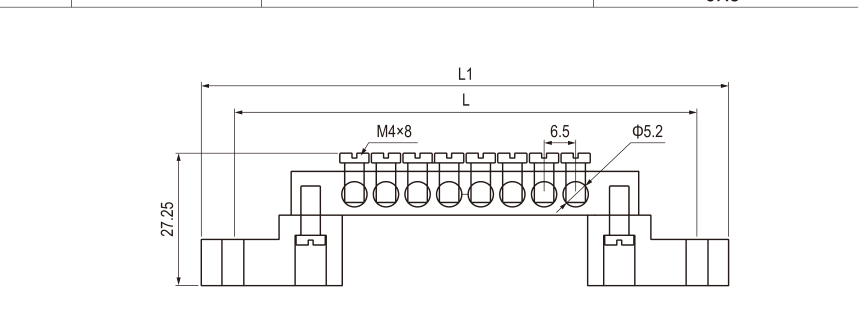
Choose CS004-0609 by connection-position count, 6 × 9 mm brass section and fixing-centre distance. Use the dimension table to reserve mounting space.
Connection-position options are 4, 6, 8, 10, 12, 14, 16. The bar section is 6 × 9 mm; overall lengths are listed for each option.
No. All screws along one continuous brass bar share a common potential. Use separate bars where separate potentials are required.
No. Bore diameter and brass dimensions describe geometry. Conductor construction, ferrule size, clamping engagement and temperature rise must also suit the assembly.
No. Colour is an identification aid. Protective-earthing use also requires a suitable verified connection and bonding arrangement; do not infer it from blue or green plastic alone.
Include CS004-0609 Neutral Terminal Bar model code, quantities, conductor sizes, destination and packaging requirements.
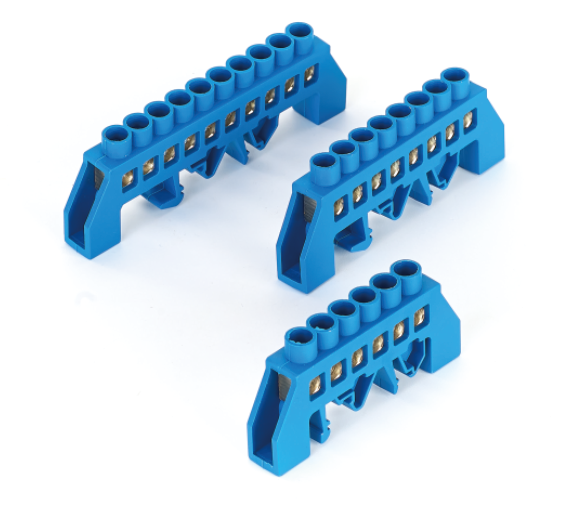
6 × 9 mm brass · 6–12 positions · Bridge support / DIN rail
CS001D-0609 brass neutral terminal bar with 6 × 9 mm bar section, 6–12 connection positions and DIN rail mounting.
Specifications & dimensions →
8 × 12 mm brass · 6–16 positions · Bridge support / DIN rail
CS001D-0812 brass neutral terminal bar with 8 × 12 mm bar section, 6–16 connection positions and DIN rail mounting.
Specifications & dimensions →
6 × 9 mm brass · 7–15 positions · DIN rail 35 × 7.5 mm
CS009-0609 brass neutral terminal bar with 6 × 9 mm bar section, 7–15 connection positions and DIN rail mounting.
Specifications & dimensions →